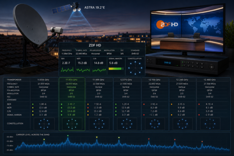
Why Astra 19.2E Works on One TV but Not Another
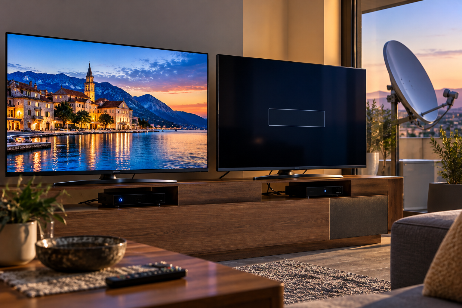
Two televisions are connected to the same Astra 19.2E satellite dish. One receives its channels perfectly. The other displays “No Signal,” loses certain transponders, or finds a completely different selection of services. The dish is shared, the satellite is the same, and the weather is identical. So why does only one television have a problem?
The answer is usually found somewhere between the dish and the individual tuner. A shared antenna does not guarantee identical electrical connections, switching commands, receiver capabilities, or signal quality. Understanding those differences can help you isolate the fault without unnecessarily replacing the dish or LNB.
If Astra 19.2E works on one TV but not another, first establish whether the two tuners have independent LNB outputs, separate multiswitch connections, or a correctly configured Unicable system. Then compare the cables, receiver settings, and specific transponders that work or fail. The functioning TV is useful evidence that part of the satellite installation works, but it does not prove that every signal path is healthy.
Why One Dish Can Produce Different Results
A satellite dish is a passive antenna that collects radio-frequency energy from a particular direction. It does not distribute a ready-made television picture to every connected screen.
Instead, the LNB converts the received satellite signals into intermediate frequencies, and each satellite tuner selects and decodes the carrier it needs.
In a conventional installation, the tuner also sends electrical commands through the coaxial cable to select the required polarization and frequency band.
Consequently, two televisions connected to the same reflector may use different LNB outputs, cables, switching equipment, and tuner settings.
If one path develops a fault, the other may continue operating normally.
This distinction matters because the working television does not automatically rule out the LNB, cabling, or distribution system.
It only demonstrates that the particular combination of hardware and settings used by that television can receive the services currently being tested.
How the Two TVs Are Actually Connected
Before troubleshooting, identify the installation’s distribution architecture.
There are several common arrangements, and each requires a different diagnostic approach.
| Installation Type | How Two Tuners Receive Signals | Common Problem |
|---|---|---|
| Universal Twin LNB | Each tuner has its own independently controlled LNB output | One output or cable fails |
| Universal Quad LNB | Each tuner uses a separate output | Faulty output, connector, or cable |
| Quattro LNB with multiswitch | The multiswitch distributes selected signal groups to each tuner | Faulty subscriber port or switching path |
| Unicable/SCR or dCSS | Multiple tuners share a compatible single-cable distribution system | User-band conflicts or incorrect receiver settings |
| Conventional LNB with passive splitter | Two tuners share a control path not designed for independent selection | Band or polarization conflicts |
A standard universal LNB output should not simply be split between two independently operating receivers with an ordinary passive splitter.
Both tuners may attempt to control the same LNB output, requesting different polarization or band selections.
Depending on the splitter, receiver protection circuitry, and control conditions, reception can become unreliable or limited to certain channels.
Independent operation requires an appropriate distribution design, such as separate universal LNB outputs or a correctly configured single-cable system.
Twin and Quad LNB Output Problems
A universal Twin LNB normally provides two independently switched outputs. A universal Quad LNB generally provides four.
Each output is designed to respond to the control commands from its connected tuner.
That means one output can fail while the others continue working.
For example, one output may develop an internal switching fault, moisture damage, or an unreliable connector.
The result can look exactly like a receiver problem: one television works, while another cannot lock onto expected Astra transponders.
A controlled test can help distinguish between the two possibilities.
With both receivers powered off, and only where the installation uses compatible conventional outputs, you can interchange the two LNB output connections.
If the fault follows a particular LNB output, that output becomes a stronger suspect.
If the fault remains associated with the same cable run or television, investigate that path instead.
However, this test is not directly applicable to fixed Quattro outputs or Unicable user-band arrangements, where outputs have specific functions.
For more on replacement compatibility, read Why Astra Channels Vanish After an LNB Change.
Why One Coaxial Cable Can Fail While Another Works
Even when two televisions use the same LNB model and receiver settings, their coaxial cable paths may be different.
One cable may be longer, have more connectors, or pass through a damp exterior junction.
Another may have been sharply bent or damaged during installation.
These differences can affect both the satellite intermediate-frequency signal and the electrical control signals sent toward the LNB.
Common faults include:
- Loose F-connectors
- Corroded cable connections
- Water ingress
- Damaged center conductors
- Stray shielding strands causing a short circuit
- Excessive cable attenuation
- Faulty wall plates or intermediate connectors
A cable fault does not always produce a complete loss of signal.
Some faults reduce reception margin enough to affect particular transponders, while others interfere with voltage delivery or switching.
For example, a longer or degraded cable may introduce more attenuation at higher intermediate frequencies.
That can produce a frequency-dependent problem even though both televisions receive signals from the same satellite.
Where practical, testing the affected receiver with a short, known-good cable on a compatible output can help isolate the installation cable.
Safety: Switch off the receiver before disconnecting or reconnecting satellite coaxial cables. Never work on rooftop equipment or elevated antenna mounts without appropriate access and safety precautions.
13/18V Polarization Switching
Many Astra 19.2E services use horizontal or vertical linear polarization.
In a conventional universal LNB system, the receiver normally selects the polarization by changing the DC voltage supplied through the coaxial cable.
Approximately 13V selects vertical polarization, while approximately 18V selects horizontal polarization.
These are nominal control states; actual operating ranges depend on equipment specifications.
If one tuner cannot provide the required voltage, it may receive one polarization but fail on the other.
The problem may originate inside the receiver, at a connector, along the cable, or within the LNB’s switching circuitry.
Voltage drop becomes particularly relevant when the receiver is supplying power through a long or electrically compromised cable.
However, do not assume every missing horizontal transponder proves an 18V problem.
Other faults can produce similar symptoms.
The correct test is to compare known working and failing carriers by polarization and, where appropriate, measure the control path using suitable equipment.
For a more focused explanation, see Why Astra 19.2E Signal Drops on One Polarization.
22 kHz Band Switching
Conventional universal Ku-band LNBs commonly use two local oscillator frequencies:
- 9750 MHz for the lower band
- 10600 MHz for the upper band
The receiver normally uses a 22 kHz control tone to switch between these bands.
If the tone is absent or the LNB fails to respond, the tuner may receive one band but not the other.
This can create a particularly misleading situation.
Both televisions may receive Astra 19.2E, but one finds a much smaller channel list because it cannot access an entire frequency band.
| Control State | Typical Universal LNB Selection |
|---|---|
| 22 kHz tone off | Low band, nominal 9750 MHz local oscillator |
| 22 kHz tone on | High band, nominal 10600 MHz local oscillator |
For conventional universal LNBs, verify that the receiver is configured for the appropriate universal oscillator and automatic band-switching behavior.
Do not apply these settings blindly to Quattro multiswitch or Unicable installations, which have different control requirements.
DiSEqC Settings on Different Receivers
If the installation receives more than one satellite, the receivers may need to control a DiSEqC switch.
Each satellite feed is connected to a particular input, and the receiver sends a command to select it.
One receiver might have the correct mapping while the other uses a different configuration.
For example, suppose Astra 19.2E is physically connected to Port A and Hot Bird 13E to Port B.
If the second receiver assigns Astra to Port B, it may select the wrong satellite.
Depending on the scanning method and stored transponder data, the receiver might find unexpected channels or fail to lock onto the intended Astra carriers.
The correct port assignment is determined by the actual installation, not by a universal Astra default.
Monoblock LNBs also have product-specific switching arrangements.
If one receiver works correctly, compare its DiSEqC settings with those on the affected television.
For related scanning problems, see Why Your Receiver Finds the Wrong Astra Channels.
Multiswitch Distribution Faults
In larger installations, a Quattro LNB may feed a multiswitch that distributes satellite signals to several rooms.
A conventional Quattro LNB supplies four fixed signal groups:
- Vertical low band
- Horizontal low band
- Vertical high band
- Horizontal high band
The multiswitch selects the appropriate group for each connected conventional tuner.
If one subscriber output is faulty, a television connected to that port may lose reception while other rooms continue working.
Other possible problems include defective switching circuitry, poor connectors, distribution power faults, or incorrect LNB input mapping.
However, the failure pattern matters.
If only one room is affected, investigate its individual cable and multiswitch output.
If several rooms lose the same frequency band or polarization, investigate the shared upstream signal path.
A functioning television elsewhere in the building does not prove that every multiswitch input and output is operating correctly.
Unicable and SCR User-Band Conflicts
Unicable and dCSS systems allow compatible satellite tuners to share a coaxial distribution network while requesting their own satellite signals.
Instead of controlling a conventional universal LNB output independently, each tuner normally uses an assigned user band.
These systems may operate under EN 50494 or EN 50607, depending on the equipment.
Two televisions can therefore behave differently if their user-band settings are incorrect.
For example, both tuners may be assigned the same user band in a system where that assignment must be unique.
When both devices operate, their requests may interfere with each other.
Alternatively, the affected receiver may use the wrong user-band frequency or an unsupported control protocol.
Possible symptoms include:
- One television works while the other finds no channels
- Reception changes when the second tuner is switched on
- Channels fail intermittently when both tuners are active
- One receiver works only when the other is in standby
Check the LNB or multiswitch documentation and verify the assigned user bands, frequencies, and supported protocol.
Do not configure a Unicable system as a conventional universal LNB installation unless the hardware provides a dedicated legacy output intended for that purpose.
TV Tuner and Decoder Compatibility
Sometimes the satellite signal path is healthy, but the two televisions have different reception capabilities.
One may use a modern DVB-S2-compatible tuner, while the other supports only older transmission formats.
Some services may also use video codecs that an older television cannot decode.
It is important to distinguish between three different failure stages.
| Failure Stage | Typical Symptom | What to Investigate |
|---|---|---|
| RF acquisition | No carrier lock | Signal path, tuner standard and transmission parameters |
| Service discovery | Transponder locks but channel is not listed | Scan settings and service information |
| Service playback | Channel appears but picture or audio is unavailable | Codec support, encryption and decoder capability |
A service that appears in the channel list but cannot be decoded is not necessarily suffering from weak satellite reception.
For encrypted services, the television or receiver may require compatible conditional-access equipment and valid authorization.
Likewise, an unsupported video codec may prevent playback even when the RF carrier is received correctly.
Before adjusting the antenna, establish whether the affected television actually fails to lock onto the transponder or merely fails to display the service.
What the Failure Pattern Tells You
Comparing symptoms between the two televisions can narrow the fault considerably.
| Observed Pattern | Likely Area to Investigate | Useful First Test |
|---|---|---|
| One TV receives nothing | Connection, tuner settings, LNB output or power | Compare configurations and test a known-good connection |
| One TV loses only horizontal channels | Polarization switching or distribution path | Compare known H and V transponders |
| One TV loses high-band channels | 22 kHz switching or LNB configuration | Compare low-band and high-band carriers |
| Problem appears only when both TVs are on | Improper splitting or Unicable conflict | Inspect distribution architecture and user bands |
| One TV finds channels but cannot display them | Decoder, codec or conditional access | Check carrier lock and service compatibility |
| One room has weaker quality on several carriers | Cable loss, connectors or multiswitch output | Test the receiver on a known-good path |
| Both TVs lose the same channels | Shared reception path or transponder-specific issue | Check the common LNB and antenna system |
These patterns are diagnostic clues, not definitive proof.
For example, losing horizontal channels suggests a polarization-control problem, but it does not identify whether the fault is inside the tuner, cable, LNB, or multiswitch.
Controlled testing is necessary to isolate the responsible component.
Step-by-Step Fault Isolation
Step 1: Compare the Same Transponder
Start by testing the same verified Astra 19.2E transponder on both televisions.
Use the same frequency, polarization, symbol rate, and relevant transmission settings.
Comparing different channels on different transponders can lead to misleading conclusions.
Step 2: Check Whether the Tuner Locks
Determine whether the affected television actually locks onto the carrier.
If it locks but cannot display the service, investigate scanning, decoding, or conditional access before changing antenna equipment.
Step 3: Compare Receiver Configuration
Check the satellite entry, LNB type, local oscillator frequencies, DiSEqC assignment, and any Unicable settings.
Do not assume that two receivers use identical default settings.
Step 4: Identify the Distribution System
Determine whether the tuners use independent universal LNB outputs, a multiswitch, or a Unicable system.
This determines which connection tests are appropriate.
Step 5: Test a Known-Good Signal Path
Where the hardware is compatible and accessible, connect the affected receiver to a signal path known to work.
Power off the equipment before moving coaxial connections.
If the receiver works on the known-good path, the original cable or distribution output becomes a stronger suspect.
Step 6: Test Band and Polarization Groups
Use verified transponders to compare horizontal and vertical reception as well as low-band and high-band operation.
This can reveal switching faults that a single channel test would miss.
Step 7: Inspect Cables and Connectors
Check accessible F-connectors, wall plates, cable bends, and signs of moisture damage.
Do not disconnect live satellite coaxial cables or attempt electrical measurements without suitable equipment and competence.
Step 8: Verify Unicable or Multiswitch Configuration
For Unicable systems, check user-band assignments and supported standards.
For multiswitch installations, verify subscriber outputs and the relevant shared inputs.
Step 9: Compare Real Signal Measurements
Where possible, compare MER, C/N, and error performance using suitable diagnostic equipment.
Receiver quality percentages are not standardized across brands and may not be directly comparable.
For additional context, see Why Signal Quality Matters More Than Signal Strength.
Step 10: Replace Equipment Only After Isolating the Fault
If the fault follows one LNB output, receiver, cable, or multiswitch port during controlled testing, replacement or repair can be targeted.
Avoid changing several components simultaneously, because doing so makes it difficult to identify the actual cause.
Reality Check
One working television does not prove that the entire Astra 19.2E installation is healthy.
It proves that one particular receiving path can deliver the tested services.
A second tuner may have a different cable, LNB output, switching configuration, multiswitch port, or decoder capability.
Likewise, a blank television screen does not automatically mean the satellite signal is absent. The tuner may be locked onto a valid carrier while the service remains unavailable because of scanning, codec, or conditional-access limitations.
The correct diagnosis begins by separating RF reception problems from service playback problems, then comparing equivalent transponders and signal paths.
Final Verdict
If Astra 19.2E works on one TV but not another, investigate the individual signal path before touching the dish alignment.
Start by checking whether both televisions are connected through independent universal LNB outputs, a compatible multiswitch, or a correctly configured Unicable distribution system.
Next, compare the same transponder on both devices and determine whether the affected tuner fails to lock or merely fails to decode the service.
Missing polarization groups can indicate voltage-switching faults. Missing frequency bands can suggest 22 kHz control problems. Failures that appear only when both televisions operate may indicate distribution conflicts.
Finally, use controlled connection tests to determine whether the problem follows a receiver, cable, LNB output, or multiswitch port.
The dish may be shared, but satellite reception depends on the complete path from the antenna feed to each tuner. That is why two televisions can produce very different results from the same Astra 19.2E installation.
Frequently Asked Questions
| Question | Answer |
|---|---|
| Why does Astra work on one TV but show no signal on another? | The affected TV may have a faulty cable or LNB output, incorrect tuner settings, a distribution problem, or incompatible reception hardware. |
| Can one output of a Twin LNB fail while the other works? | Yes. Independent outputs can develop separate faults, including switching or connector problems. |
| Can I connect two satellite receivers to one LNB cable? | Independent operation generally requires a suitable distribution system. A conventional universal output should not simply be split between two independently controlled tuners. |
| Why do some channels work on both TVs but others work on only one? | Possible causes include band or polarization switching faults, frequency-dependent cable loss, tuner compatibility, or service decoding differences. |
| Can different DiSEqC settings cause the problem? | Yes. One receiver may select the correct Astra LNB while the other activates a different switch input. |
| Why does the second TV stop working when the first is switched on? | Check for improper cable splitting or conflicting Unicable user-band assignments, depending on the installation. |
| Can an older TV fail to receive channels that a newer receiver supports? | Yes. Differences in DVB transmission support, video codecs, and conditional-access compatibility can affect which services are available. |
| Should I realign the dish if one TV works? | Not as the first step. Compare the individual reception paths and tuner configurations before adjusting a shared antenna. |
| Will replacing the LNB fix the second television? | Only if the LNB or one of its outputs is responsible. Verify the fault before replacing equipment. |
| What is the fastest way to identify the problem? | Compare the same known transponder on both tuners, verify their settings, and test the affected receiver on a compatible known-good signal path. |