Why Hot Bird Works but Some Frequencies Stay Weak
Your satellite receiver locks onto Hot Bird 13°E, several channels play without interruption, and the dish appears to be properly aligned. Yet some frequencies remain noticeably weaker than others. A few may even fail to lock while neighboring transponders continue working normally.
This is not necessarily a contradiction. Receiving one Hot Bird transponder does not prove that every carrier at 13°E has sufficient reception margin. Different transmission parameters, dish alignment, LNB behavior, cable losses, and interference can all affect individual frequencies. The useful question is not simply whether Hot Bird works, but why particular transponders perform worse than the rest.
Hot Bird 13°E is an orbital position served by Eutelsat’s HOTBIRD 13F and 13G satellites. A receiver evaluates individual carriers rather than one universal signal for the entire orbital position. Weak frequencies should therefore be investigated through their actual lock status, modulation parameters, MER or C/N measurements, and the condition of the receiving installation.
Why Hot Bird Is Not One Uniform Signal
One of the most common misunderstandings in satellite reception is treating an orbital position as a single signal source with one fixed strength.
Hot Bird 13°E carries numerous transponders, and each carrier has its own frequency, polarization, symbol rate, and transmission configuration. Depending on the service and satellite resources involved, reception conditions may differ.
Eutelsat identifies HOTBIRD 13F and HOTBIRD 13G as the satellites serving this orbital position. Their coverage is designed for broadcasting across Europe, North Africa, and the Middle East, but this does not mean every receiving installation will deliver an identical margin on every transponder.
A successful lock on one frequency confirms that the system can receive that particular carrier under the current conditions. It does not establish the performance of other carriers.
Even transponders within broadly similar coverage areas can show different reception results because of transmission characteristics and the response of the receiving equipment.
Why Transponders Have Different Reception Margins
Digital satellite reception depends on more than the amount of RF power reaching the receiver.
A transponder must provide sufficient carrier quality for the receiver to demodulate its signal and recover the transmitted data reliably.
Modulation and FEC Requirements
Different DVB-S and DVB-S2 transmission configurations can require different carrier-to-noise conditions.
For example, a transmission using a higher-order modulation scheme may require a cleaner signal than another transmission using a more robust configuration. Forward error correction also affects how much impairment a signal can tolerate.
Consequently, two transponders with similar measured RF levels may have different decoding margins.
This does not mean every DVB-S2 carrier requires more signal than every DVB-S carrier. The actual requirement depends on the modulation, coding rate, implementation, and operating conditions.
Coverage and Available Link Margin
Satellite antenna patterns and available downlink power also contribute to reception performance.
The relevant engineering concept is link margin: how far the received signal quality remains above the level needed for reliable demodulation.
When margin is generous, modest variations may have no visible effect. When margin is small, minor degradation can cause freezing, intermittent lock, or complete loss of reception.
What Signal Quality Measurements Actually Mean
Many receivers display a signal-strength percentage and a signal-quality percentage. These indicators can help identify changes on the same equipment, but they should not be treated as standardized engineering measurements.
| Measurement | What It Indicates | Diagnostic Value |
|---|---|---|
| Signal Level | Received RF power or an equipment-specific level indication | Helps identify attenuation or unusually high input levels |
| C/N | Carrier power relative to noise power in a defined bandwidth | Helps evaluate reception conditions and margin |
| MER | Modulation error relative to the ideal constellation | Reveals combined modulation impairments |
| BER | Bit error rate at a specified processing stage | Indicates data errors, with interpretation depending on measurement location |
| Receiver Quality % | Manufacturer-specific quality indicator | Useful mainly for relative comparisons on the same device |
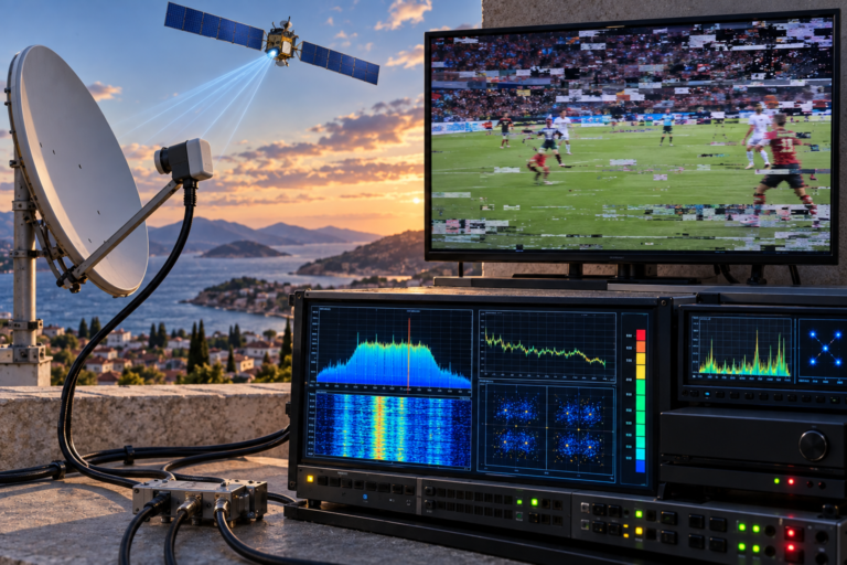
For a meaningful transponder comparison, a satellite analyzer that reports MER, C/N, and relevant error measurements is generally more informative than an ordinary receiver percentage display.
However, measurements must still be interpreted against the operating requirements of each carrier. A higher MER reading is normally favorable, but the required margin is not identical across all transmission modes.
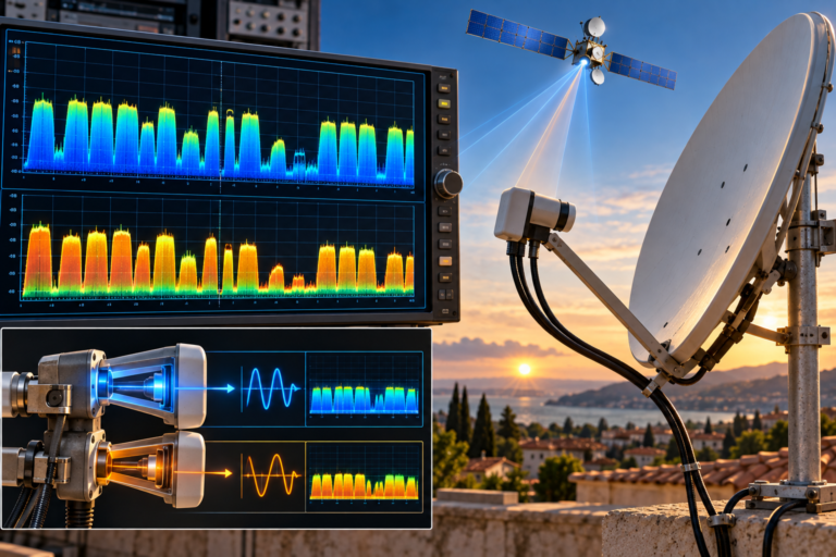
How an LNB Can Affect Certain Frequencies
The low-noise block downconverter, or LNB, receives the Ku-band signal collected by the dish and converts it into a lower intermediate frequency for delivery through coaxial cable.
A universal LNB typically uses nominal local oscillator frequencies of 9,750 MHz for the lower band and 10,600 MHz for the upper band.
The LNB’s performance is not necessarily identical across its entire operating range.
Frequency Response and Conversion Performance
Gain, noise performance, impedance matching, and conversion characteristics can vary with frequency.
A properly functioning LNB is designed to operate within specified tolerances. But aging components, moisture damage, manufacturing defects, or unsuitable hardware can introduce more significant variation.
If weak transponders consistently occupy a particular portion of the receiving band, LNB behavior becomes one possible explanation.
That pattern is useful evidence, but it is not enough by itself to confirm an LNB fault.
Local Oscillator Stability
Excessive local oscillator frequency error or instability can also interfere with carrier acquisition.
Satellite receivers can compensate for some frequency offset, but their acquisition and tracking ranges are finite.
If an aging LNB becomes unstable when heated, frequencies that already have limited reception margin may fail first.
This type of temperature-dependent behavior is explored in our related guide, Why Astra Works at Night but Weakens by Day. Although that article examines Astra reception, the underlying issues involving LNB temperature, oscillator stability, and marginal RF performance are relevant to Ku-band reception troubleshooting more broadly.
Temperature alone does not prove that an LNB is defective. A healthy unit should tolerate normal operating conditions within its specifications. Investigate excessive drift only when the observed pattern supports it.
Why Cable Loss Is Frequency-Dependent
Once the LNB converts the satellite signal, the resulting satellite intermediate frequency travels through the coaxial distribution system.
In a conventional universal LNB installation, this IF signal is typically within approximately 950–2150 MHz.
Coaxial cable attenuation generally increases with frequency. The exact loss depends on the cable construction, length, connectors, and operating conditions.
This introduces an important distinction:
- The satellite’s original downlink frequency is not the same as the frequency traveling through the cable.
- Different satellite transponders may be converted into different IF positions.
- A weak cable path can disproportionately affect portions of the IF spectrum.
For example, in a lower-band universal LNB configuration, a hypothetical 11,500 MHz downlink carrier would produce a nominal IF of 1,750 MHz using a 9,750 MHz local oscillator.
That is an illustrative conversion calculation, not a claim about a currently active Hot Bird transponder.
Higher cable attenuation does not automatically mean lower MER. If the received carrier remains well above the system’s noise and interference limitations, additional loss may primarily reduce signal level. Quality becomes affected when attenuation, noise contributions, mismatch, or other impairments reduce usable margin.
Connectors and Moisture Damage
A damaged F-connector, poorly terminated cable, or moisture-contaminated joint can introduce mismatch, attenuation, or unstable contact.
Some faults produce frequency-selective behavior rather than a uniform reduction across every carrier.
If one receiver has weak frequencies while another receiver connected to the same dish works normally, investigate the individual signal paths.
Our article Why Astra 19.2E Works on One TV but Not Another explains how independent LNB outputs, coaxial runs, switching equipment, and tuner settings can produce different reception results even when the reflector is shared. The same distribution principles help diagnose Hot Bird installations.
Dish Alignment and Polarization Errors
A dish that successfully receives Hot Bird is not necessarily aligned for maximum usable signal margin.
A small pointing error may go unnoticed on robust transponders while reducing the stability of carriers with less available margin.
That is why professional alignment should aim for reliable reception quality rather than simply achieving a lock or maximizing an arbitrary signal-strength bar.
Fine Pointing and Antenna Gain
Accurate azimuth and elevation adjustments help place the antenna’s main reception beam toward the intended orbital position.
Mechanical movement, an unstable mounting pole, or imperfect initial alignment can reduce performance.
A careful adjustment using a suitable analyzer should compare multiple relevant transponders instead of optimizing only one convenient frequency.
LNB Skew and Polarization Isolation
Hot Bird broadcasts using linear polarization. Proper feed rotation helps the receiving antenna discriminate between horizontal and vertical components.
Incorrect LNB skew can reduce polarization isolation and increase susceptibility to unwanted signals on the opposite polarization.
The impact may be more noticeable on certain transponders, depending on their reception margin and surrounding interference conditions.
However, skew adjustment should not be used as a substitute for diagnosing an actual polarization-switching fault.
Frequency-Selective Interference
Not every weak frequency is caused by the dish, LNB, or satellite transmission parameters.
Interference entering the receiving system can impair particular sections of the IF spectrum.
Potential sources include poorly shielded equipment, unwanted emissions from nearby electronics, inadequate cable screening, and coupling through defective connections.
The affected frequencies depend on the interfering signal and the characteristics of the installation.
A spectrum analyzer may reveal unwanted peaks or other abnormalities, although identifying the true source can require additional testing.
Always distinguish an actual interfering carrier from ordinary transponder energy before concluding that interference is present.
What the Failure Pattern Tells You
Before replacing hardware, look for a repeatable relationship between the affected transponders.
| Observed Pattern | Possible Explanation | Useful Next Check |
|---|---|---|
| Weak frequencies cluster in one IF range | Cable response, LNB performance, or frequency-selective interference | Compare readings at different points in the cable path |
| One polarization is consistently affected | Switching, skew, or distribution-path issue | Compare verified H and V carriers across both bands |
| Weak frequencies change with temperature | Marginal equipment or environment-sensitive reception | Record measurements under repeatable conditions |
| One receiver fails but another works | Different cables, LNB outputs, settings, or tuner behavior | Compare equivalent paths and configurations |
| Several marginal carriers improve after fine alignment | Insufficient antenna pointing margin | Optimize MER across representative carriers |
| A carrier shows adequate level but poor MER | Noise, interference, distortion, or another modulation impairment | Examine spectrum and quality measurements |
These patterns help narrow the investigation. They do not provide definitive fault identification without supporting measurements.
How to Diagnose Weak Hot Bird Frequencies Step by Step
Step 1: Establish Which Transponders Are Actually Weak
Record the frequency, polarization, symbol rate, transmission standard, and lock status of each affected transponder.
Verify that the parameters are current using a reliable channel or transponder reference. Outdated receiver entries can create apparent reception problems unrelated to actual RF quality.
Step 2: Separate Signal Level From Quality
Use MER and C/N readings where supported. Record the measurements along with the carrier’s modulation and coding parameters.
If only receiver percentages are available, compare repeated readings on the same device without treating them as standardized values.
Step 3: Look for a Band or Polarization Pattern
Determine whether the affected carriers share a polarization, an LNB frequency band, or a narrow part of the converted IF spectrum.
A consistent grouping can help identify switching or distribution problems that a random list of weak channels would conceal.
Step 4: Test the Signal Path
Where practical, compare measurements closer to the LNB and at the receiver input using suitable equipment and safe procedures.
A significant deterioration along the path suggests that cables, connectors, switches, or distribution components deserve attention.
In multiswitch or Unicable installations, tests must account for the system’s specific architecture. Do not assume that a direct universal-LNB procedure applies to every distribution network.
Step 5: Check Alignment Across Several Carriers
Use a calibrated or otherwise suitable satellite analyzer to assess representative transponders.
Make small, controlled azimuth and elevation adjustments only when the measurements indicate that pointing is contributing to the problem.
Then assess LNB skew separately.
Step 6: Isolate Components Instead of Replacing Everything
If possible, test with a known-good compatible LNB, a verified cable run, or another receiver.
Change one variable at a time and repeat the same measurements.
Disconnect equipment power before handling coaxial connections, and avoid creating shorts or incompatible switching arrangements.
The strongest troubleshooting result is not a higher signal percentage after several adjustments. It is a repeatable measurement showing which component or configuration change improves the affected carriers without degrading otherwise healthy reception.
Will a Larger Dish Fix Weak Hot Bird Frequencies?
A larger reflector can increase receiving antenna gain when correctly designed, installed, and aligned.
That improvement can help transponders whose main limitation is insufficient carrier-to-noise margin at the antenna.
But additional antenna gain will not automatically repair a defective LNB switch, serious cable mismatch, unstable local oscillator, incorrect receiver configuration, or a frequency-selective fault introduced farther down the signal path.
Before changing dish size, determine whether the receiving system is genuinely limited by available link margin.
Dish diameter should be evaluated alongside local coverage conditions, antenna efficiency, pointing accuracy, weather margin, and overall system performance.
Reality Check: A Working Satellite Is Not a Healthy Signal Path
Receiving several Hot Bird channels proves that part of the system is functioning. It does not prove that every frequency has adequate MER, that both polarization paths are healthy, or that the coaxial distribution system performs consistently across its operating band.
Equally, one weak transponder does not automatically prove that the satellite is transmitting abnormally or that the LNB must be replaced.
The diagnosis should follow the measured failure pattern, not assumptions based on a signal-strength percentage.
Final Verdict
Hot Bird 13°E can work normally on many frequencies while others remain weak because transponders do not necessarily have identical reception requirements or available margins.
Differences in modulation, coding, antenna alignment, LNB performance, cable attenuation, polarization isolation, and interference can expose weaknesses that remain invisible on more robust carriers.
The most effective solution is to verify the affected transponder parameters, measure usable signal quality, identify any band or polarization pattern, and isolate each part of the signal chain before replacing equipment.
Frequently Asked Questions
Why are some Hot Bird frequencies weaker than others?
Different transponder characteristics and reception margins can produce different results. LNB performance, alignment, cable loss, and interference may also affect individual carriers.
Can an LNB receive some Hot Bird transponders but fail on others?
Yes. Frequency-dependent defects, conversion instability, and switching problems can affect selected transponders. However, the failure pattern should be measured before blaming the LNB.
Does DVB-S2 always need a stronger signal than DVB-S?
No. Reception requirements depend on modulation, coding rate, and other transmission parameters. DVB-S2 includes operating modes with different efficiency and robustness characteristics.
Can a coaxial cable make certain Hot Bird frequencies weaker?
Yes. Cable loss and mismatch can vary across the satellite IF spectrum. The effect becomes important when the signal path reduces the available quality margin or introduces additional impairments.
Should I perform a full rescan when Hot Bird frequencies are weak?
A rescan can correct outdated service information or scan parameters, but it cannot repair insufficient RF quality. Establish whether the receiver can lock onto the affected carrier before changing the channel database.
Will a bigger satellite dish improve weak Hot Bird frequencies?
It can help when inadequate antenna gain is the principal limitation. It will not fix every LNB, switching, cable, receiver, or interference problem.