What Happens Inside a Satellite Receiver
Estimated Reading Time: 12 minutes
A satellite receiver appears simple from the outside. You select a channel, wait a moment, and a television picture appears. Inside the box, however, several different engineering systems are working continuously. The receiver must select a weak RF carrier, synchronize with its timing and phase, demodulate millions of symbols, repair damaged digital information, rebuild the programme data, decode compressed video and audio, and keep everything synchronized for the television.
This internal chain explains many satellite reception problems that otherwise seem confusing. A receiver can show strong signal but no picture because RF detection happens before DVB-S2 decoding. It can display a perfect picture while BER is already increasing because Forward Error Correction hides many errors. It can also lock a transponder successfully yet fail to show video because the final codec is unsupported. Each symptom points toward a different processing stage.
A modern satellite receiver performs three broad jobs. First, it receives and demodulates the RF signal supplied by the LNB. Second, it reconstructs the protected digital stream using DVB-S2 synchronization and Forward Error Correction. Third, it separates the selected service and decodes its compressed video and audio. A fault can occur at any of these stages, so “no picture” does not automatically mean “no satellite signal.”
- The Signal Arrives From the LNB
- What the Tuner Front End Does
- Why Automatic Gain Control Matters
- How the Receiver Finds the Carrier
- Symbol Timing and Synchronization
- How QPSK and 8PSK Become Digital Bits
- What MER Tells the Demodulator
- How BER Appears Inside the Receiver
- How LDPC and BCH Repair Damaged Data
- How the Receiver Recovers DVB-S2 Frames
- From DVB-S2 Data to the Transport Stream
- What the Demultiplexer Does
- Why the Receiver Uses Buffers
- How Video and Audio Are Decoded
- How Audio and Video Stay Synchronized
- Why a Receiver Can Lock but Show No Picture
- What Happens When Signal Quality Collapses
- Reality Check
- Final Verdict
- FAQ
The Signal Arrives From the LNB
The receiver does not normally receive the original Ku-band satellite frequency directly. The LNB mounted at the dish amplifies the weak microwave signal and converts it to a lower intermediate frequency that can travel through coaxial cable.
The same cable also carries DC power and control signals from the receiver toward the LNB. Voltage is commonly used to select polarization, while a 22 kHz tone can control low-band and high-band selection in a Universal LNB system.
By the time the signal reaches the receiver input, it is still an RF waveform containing the complete transponder. No television picture has been decoded yet.
What the Tuner Front End Does
The tuner selects a narrow portion of the incoming satellite intermediate-frequency spectrum corresponding to the requested transponder.
It must know parameters such as frequency, symbol rate, and polarization configuration. The receiver may obtain these settings from a stored channel list, a manual scan, or a blind scan.
The tuner filters unwanted frequencies and converts the selected signal into a form suitable for digital demodulation.
This is why incorrect tuning data can produce high signal strength without a valid channel. RF energy may be entering the tuner, but the requested DVB-S2 carrier is not being selected correctly.
Why Automatic Gain Control Matters
Satellite signal levels can vary considerably between installations and transponders. The receiver therefore uses Automatic Gain Control, normally shortened to AGC, to keep internal signal levels within a useful range.
Many consumer receivers derive their signal-strength percentage partly from AGC information. This is one reason a high strength reading should not be confused with successful DVB-S2 decoding.
AGC primarily tells the receiver about signal level. It does not confirm that the modulation is clean, that BER is low, or that the correct transport stream has been recovered.
How the Receiver Finds the Carrier
After the tuner isolates the requested frequency region, the demodulator must locate the exact carrier.
The frequency delivered by the LNB may not match the theoretical value perfectly because the LNB oscillator has some frequency tolerance and temperature-dependent drift.
Carrier recovery circuitry estimates this offset and tracks the received signal. It must also recover the correct phase reference required for phase-based modulation such as QPSK and 8PSK.
If carrier quality becomes too poor, the receiver can no longer maintain reliable tracking and eventually loses lock.
Symbol Timing and Synchronization
The satellite carrier transports information as symbols transmitted at a defined symbol rate.
The receiver must determine exactly when each symbol should be measured. Sampling at the wrong instant makes constellation points less accurate and increases the probability of an incorrect decision.
Timing recovery therefore operates continuously alongside carrier recovery.
DVB-S2 also uses structured physical-layer framing so the receiver can identify frame boundaries and understand how the following symbols should be processed. ETSI defines DVB-S2 as a system using physical-layer framing, modulation, and BCH plus LDPC Forward Error Correction. :contentReference[oaicite:0]{index=0}
How QPSK and 8PSK Become Digital Bits
Once synchronization is established, the demodulator interprets the received constellation.
QPSK contains four principal symbol states and therefore represents two bits per symbol. 8PSK contains eight states and represents three bits per symbol.
The demodulator measures the phase and amplitude of each received symbol and determines which valid constellation point it most likely represents.
Noise, interference, phase instability, poor dish alignment, and LNB errors move measured symbols away from their ideal positions. When the movement becomes large enough, the receiver chooses the wrong symbol and produces incorrect bits.
What MER Tells the Demodulator
MER, or Modulation Error Ratio, describes how accurately the received constellation matches its ideal symbol positions.
High MER means the symbol clusters are relatively clean and well separated. Lower MER means the constellation has become more disturbed by noise, interference, phase errors, or distortion.
MER is valuable because it can reveal declining reception quality even while the picture remains perfect.
The receiver may still be correcting every resulting error, but the distance between current performance and complete decoding failure is becoming smaller.
How BER Appears Inside the Receiver
When the demodulator selects an incorrect symbol, one or more incorrect bits may result.
BER, or Bit Error Rate, measures the frequency of these digital errors. Pre-FEC BER describes the errors present before Forward Error Correction has repaired them.
A receiver can have measurable pre-FEC errors while displaying flawless television because DVB-S2 was specifically designed to correct transmission errors before the programme data reaches later decoding stages.
When signal quality deteriorates further, the number of raw errors rises until the correction system can no longer recover everything successfully.
| Receiver Stage | Main Job | Typical Fault Symptom |
|---|---|---|
| Tuner | Select the requested RF carrier | Strong RF reading but no valid lock |
| Carrier recovery | Track frequency and phase | Intermittent lock or complete signal loss |
| Symbol timing | Sample symbols at the correct moment | Higher BER and unstable demodulation |
| Demodulator | Recover QPSK or 8PSK symbol information | Low MER and increasing bit errors |
| LDPC and BCH decoder | Repair damaged digital information | Pixelation when correction capacity is exceeded |
| Transport processing | Recover and separate programme streams | Missing video, audio, or service information |
| Video decoder | Decode H.264, HEVC, or another codec | Channel identified but video remains black |
| Output stage | Send decoded video and audio to television | HDMI or display problems despite successful reception |
How LDPC and BCH Repair Damaged Data
DVB-S2 uses Low-Density Parity-Check coding as its main Forward Error Correction system, combined with an outer BCH code. :contentReference[oaicite:1]{index=1}
LDPC processing uses structured redundancy in the transmitted data to estimate the most likely original codeword when errors are present.
The decoder can perform iterative processing, progressively improving its estimate until a valid result is produced or the correction process reaches its practical limit.
BCH protection provides another correction layer for residual errors.
This powerful error-correction chain is a major reason digital satellite television can remain visually perfect even while the RF signal is already deteriorating.
How the Receiver Recovers DVB-S2 Frames
The receiver does not process one endless, unstructured sequence of symbols. DVB-S2 organizes transmitted information into defined physical and Forward Error Correction frame structures.
Physical-layer signaling tells the receiver important information about how the following transmission is configured.
After demodulation and FEC processing, the receiver reconstructs the underlying baseband frames and recovers the input data delivered to the DVB-S2 modulator at the transmitting side.
This structured framing allows the receiver to reverse the transmission process logically rather than guessing how incoming bits should be interpreted.
From DVB-S2 Data to the Transport Stream
For conventional satellite television, the recovered payload commonly contains an MPEG transport stream carrying several services.
This transport stream may contain multiple television channels, radio services, subtitles, programme information, timing references, and other data.
At this stage the DVB-S2 demodulation process has essentially delivered the digital payload successfully. The receiver must now determine which parts belong to the channel selected by the viewer.
What the Demultiplexer Does
A transport stream contains packets identified by numerical Packet Identifiers, normally called PIDs.
The receiver reads programme tables to determine which video PID, audio PID, subtitle streams, and timing information belong to the chosen service.
The demultiplexer then separates those components from the larger multiplex.
This explains why several television channels can share one transponder while the receiver displays only the selected service.
It also explains why damage to one transponder can affect multiple channels simultaneously. They share the same RF carrier and part of the same DVB-S2 recovery chain before being separated inside the receiver.
Why the Receiver Uses Buffers
Digital processing does not occur instantaneously at every stage. Receivers therefore use memory buffers to hold temporary amounts of compressed data.
Buffers help manage timing differences between transport stream arrival, demultiplexing, video decoding, audio decoding, and display output.
They are different from the large network buffers associated with internet streaming. A normal satellite broadcast arrives continuously through the DVB-S2 carrier rather than being downloaded from a remote server in bursts.
If incoming data becomes badly damaged, however, the decoder buffer may run out of usable information. The receiver can then freeze the last valid frame while waiting for enough correct data to resume decoding.
How Video and Audio Are Decoded
After demultiplexing, the compressed video stream enters the appropriate codec decoder.
Depending on the service, this may involve MPEG-2, H.264/AVC, HEVC, or another supported format.
The video decoder reconstructs complete picture frames from compressed data, including intra-coded information, motion prediction, transform coefficients, and reference frames.
Audio is decoded separately using its own codec and buffer.
This stage is completely different from DVB-S2 demodulation. A receiver may recover the satellite carrier and transport stream perfectly yet fail at the video stage because it does not support the codec used by the service.
How Audio and Video Stay Synchronized
The transport stream carries timing information that allows the receiver to maintain a common presentation timeline.
Video and audio packets may travel through different decoding pipelines and require different processing times. The receiver uses timestamps and clock references to determine when each decoded component should be presented.
Buffers absorb small timing differences so the viewer hears dialogue at the correct moment relative to the picture.
If packets are lost or the decoder becomes overloaded, temporary lip-sync errors can appear until the receiver restores stable timing.
Why a Receiver Can Lock but Show No Picture
Successful carrier lock proves only that the earlier RF and DVB-S2 stages are functioning.
The channel can still fail later in the processing chain.
An older receiver may support DVB-S2 but not HEVC. It may recover the transport stream, identify the service name, display programme information, and possibly play audio without decoding the video.
A conditional-access problem can also prevent an otherwise correctly received service from being presented. An HDMI configuration or output fault can create another type of black screen even after successful decoding.
Troubleshooting therefore requires identifying the last stage that is definitely working rather than treating every missing picture as an antenna problem.
What Happens When Signal Quality Collapses
When rain, dish misalignment, LNB problems, interference, or cable faults reduce signal quality, the failure usually develops through several internal stages.
MER falls first as the constellation becomes less accurate. Pre-FEC BER rises because the demodulator makes more incorrect symbol decisions.
LDPC and BCH initially repair the damage, so the picture remains stable.
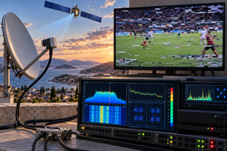
When the error-correction limit is exceeded, corrupted programme data reaches later stages. Video blocks appear, audio may click or mute, and the decoder can hold the last valid frame.
Further deterioration causes DVB-S2 frame synchronization or carrier lock to fail completely.
For a detailed view of the physical-layer stages that make this entire chain possible, see our guide explaining how DVB-S2 really works from satellite signal to TV picture. It connects the receiver processes described here with the framing, modulation, and Forward Error Correction used before the signal reaches your home.
A receiver’s signal-strength and quality percentages are usually manufacturer-specific indicators rather than universal calibrated engineering measurements.
A strong signal bar does not prove that carrier synchronization, DVB-S2 decoding, transport recovery, video decoding, and display output are all working.
The best diagnostic approach is to follow the signal through the receiver logically: RF detection, carrier lock, MER and BER, transport stream recovery, service identification, codec support, and finally video and audio output.
A satellite receiver is a complete RF and digital processing system, not simply a channel selector.
It tunes the intermediate-frequency signal from the LNB, controls signal level, acquires the carrier, restores symbol timing, demodulates QPSK or 8PSK, measures reception quality, repairs errors using DVB-S2 Forward Error Correction, reconstructs the underlying data stream, separates the selected programme, buffers compressed media, decodes video and audio, and maintains synchronization before delivering the final picture to the television.
Understanding these stages makes satellite troubleshooting much more precise. A strong RF signal can fail before demodulation. A clean DVB-S2 lock can fail at the codec stage. Pixelation can begin only after FEC runs out of correction margin. Every symptom tells you something about where the processing chain is beginning to break.
| Question | Answer |
|---|---|
| Does the satellite receiver receive Ku-band directly? | Normally no. The LNB converts the satellite signal to a lower intermediate-frequency range before sending it through the coaxial cable. |
| What does the tuner do? | It selects the required transponder frequency from the incoming RF spectrum and prepares it for digital demodulation. |
| Why does the receiver need carrier synchronization? | It must track the exact frequency and phase of the wanted carrier before it can identify modulation symbols reliably. |
| What does the DVB-S2 demodulator do? | It interprets received QPSK, 8PSK, or other supported modulation symbols and converts them into coded digital information. |
| What happens when BER increases? | Forward Error Correction must repair more damaged information. Visible problems begin when errors exceed the available correction capability. |
| What do LDPC and BCH do? | They provide DVB-S2 Forward Error Correction that helps the receiver reconstruct data damaged during transmission. |
| What is a transport stream? | It is a structured digital stream that can carry multiple television, radio, subtitle, timing, and service-information components. |
| What does the demultiplexer do? | It selects the video, audio, subtitles, and other packets belonging to the chosen television service. |
| Why does a receiver need buffers? | Buffers temporarily store data so transport processing, video decoding, audio decoding, and presentation timing can operate smoothly. |
| Can a receiver have DVB-S2 lock but no video? | Yes. The DVB-S2 transmission may be recovered correctly while the receiver lacks support for the channel’s video codec or another service requirement. |
| Why does the picture freeze when reception becomes weak? | The decoder may hold the most recent valid frame when damaged or missing data prevents reconstruction of a new picture. |
| Does high signal strength prove the receiver is decoding correctly? | No. Strength indicates RF level. Successful television reception also requires synchronization, good MER, manageable BER, valid transport data, and compatible media decoding. |